COMPUTER ELECTRONICS
IBM PC DB-25 Parallel port
description & pinout (centronix)
Controlling IBM parallel port lines
Msdos interlink cable or Lap-link cable using
IBM parallel port
Msdos interlink cable using IBM serial port NULL-MODEM
IBM PC DB-25 Serial port description & pinout (uart)
Scart (TV) connector description
IBM Vga standard Mini D-Sub 15 pin connector pinout
IBM PC-AT mini DB-9 serial port connector & pinout (uart)
IBM PC DB-15 joystick connector & pinout (game port)
IBM PC AT 5-pin DIN Keyboard connector pinout
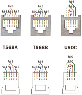
UTP jacks for all network connections
| pin | description | pin | description |
| 1 | strobe | 14 | auto feed |
| 2 | db 0 | 15 | error |
| 3 | db 1 | 16 | initialize printer |
| 4 | db 2 | 17 | select input |
| 5 | db 3 | 18 | ground |
| 6 | db 4 | 19 | ground |
| 7 | db 5 | 20 | ground |
| 8 | db 6 | 21 | ground |
| 9 | db 7 | 22 | ground |
| 10 | acknoledge | 23 | ground |
| 11 | busy | 24 | ground |
| 12 | paper out | 25 | ground |
| 13 | select |
. | . |
Controlling Centronix using a PC-IBM (parallel port)
With parallel port you can
control 4 out-swich, and 5 in-swich. Try to connect a led between pin 1 and
pin 25 (the shortest wire to this pin). Then you can control by software this
Led using information that follows (Control Output register)
(&H is Hexadecimal)
| Hardware Required | "Software" Port Address |
| Monocromatic Display Adaptor (MDA) parallel port | &H3BC |
| Primary parallel port | &H378 |
| Secondary parallel port | &H278 |
| Third parallel port (same address of MDA parallel port) | &H3BC |
| Bit | Description |
| 0 | not used |
| 1 | not used |
| 2 | not used |
| 3 | error: it's 1 if error line (pin 15) is HI |
| 4 | select: it's 1 if select line (pin 13) is HI |
| 5 | paper: it's 1 if paper line (pin 12) is HI |
| 6 | ack: it's 1 if acknoledge line (pin 10) is HI |
| 7 | busy: it's 0 if busy line (pin 11) is HI (inverting) |
to set pin 10-15 to LOW
connect it directly to ground (pin 25); To set pin 10-15 to HI disconnect it
from any other one.
3) CONTROL OUTPUT software address: Port address + 2
| Bit | Description |
| 0 | strobe: inverting, if it's 1 then strobe line (pin 1) is LOW |
| 1 | auto feed: inverting, if it's 1 then auto feed line (pin 14) is LOW |
| 2 | init: if it's 1 then initialize printer line (pin 16) is HI |
| 3 | select input: inverting, if it's 1 then select input line (pin 17) is LOW |
| 4 | enable int: it is a software control, enables interrupt request |
| 5 | not used |
| 6 | not used |
| 7 | not used |
Msdos interlink cable or Lap-link cable using IBM Parallel Port
Used to transfer data faster
than a serial cable. I've made a parallel cable 13 meters long, and it works
up to 60Kbyte per second.
| One End | Other End | Description |
| shield | shield | - |
| 2 |
15 | db-0 to error |
| 3 | 13 | db-1 to select |
| 4 | 12 | db-2 to paper out |
| 5 | 10 | db-3 to acknoledge |
| 6 | 11 | db-4 to busy |
| 10 | 5 | acknoledge to db-3 |
| 11 | 6 | busy to db-4 |
| 12 | 4 | paper out to db-2 |
| 13 | 3 | select to db-1 |
| 15 | 2 | error to db-0 |
| 25 | 25 | ground to ground |
| pin | description | pin | description |
| . | shield | 20 | input video |
| 19 | output video | 18 | ground |
| 17 | ground | 16 | blanking |
| 15 | input red | 14 | n.c. |
| 13 | ground | 12 | n.c. |
| 11 | input green | 10 | n.c. |
| 9 | ground | 8 | monitor (AV)=+12Volt |
| 7 | input blue | 6 | input audio L |
| 5 | ground | 4 | ground |
| 3 | output audio L | 2 | input audio R |
| 1 | input audio R | - | - |
Notes:this
connector is female
It's possible to make a "simple" connector from VGA to SCART but needs a bit
of eletronics for sycronism signals.
It's also possible to make a connector from SCART to VGA (example using a VGA
Monitor for video-recorder output, but I've never succeed in.
| DB-25 Pin | EIA | Description | DB-25 Pin | EIA | Description |
| 14 | SBA | secondary transmitted data | 1 | FG | protective ground |
| 15 | TC | transmitter clock | 2 | TXD | transmit data |
| 16 | SBB | secondary received data | 3 | RXD | receive data |
| 17 | RC | receiver clock | 4 | RTS | request to send |
| 18 | - | unassigned | 5 | CTS | clear to send |
| 19 | SCA | secondary request to send | 6 | DSR | data set ready |
| 20 | DTR | data terminal ready | 7 | GND | signal ground |
| 21 | SQ | signal quality | 8 | DCD | carrier detect |
| 22 | RI | ring indicator | 9 | - | reserved |
| 23 | ? | data signal rate select | 10 | - | reserved |
| 24 | ETC | external transmitter clock | 11 | - | unassigned |
| 25 | - | unassigned | 12 | SCF | secondary received line signal detector |
| - | - | - | 13 | SCB | secondary clear to send |
| DB-25 One End | DB-25 Other End | DB-9 One End | DB-9 Other End | Description |
| 1 | 1 | - | - | protective ground --- to --- protective ground |
| 2 | 3 | 3 | 2 | transmit data --- to --- receive data |
| 3 | 2 | 2 | 3 | receive data --- to --- transmit data |
| 5, 6, 8 Connect all in one |
20 | 8,6,1 Connect all in one | 4 | clear to send & data set ready & data terminal ready (of SAME SIDE): connect all in one, then with this wire --- to --- data terminal ready |
| 7 | 7 | 5 | 5 | signal ground --- to --- signal ground |
| 20 | 8, 6, 5 Connect all in one |
4 | 8,6,1 Connect all in one | data terminal ready --- to --- wire coming from clear to send & data set ready & data terminal ready (of SAME SIDE), connected all in one |
| shield | shield | shield | shield | . |
| DB-9 Pin | EIA | Description | DB-25 equivalent pin |
| 1 | DCD | data carrier detect | 8 |
| 2 | RXD | received data | 3 |
| 3 | TXD | transmit data | 2 |
| 4 | DTR | data terminal ready | 20 |
| 5 | GND | signal ground | 7 |
| 6 | DSR | data set ready | 6 |
| 7 | RTS | request to send | 4 |
| 8 | CTS | clear to send | 5 |
| 9 | RI | ring indicator | 22 |
| Pin | Joy Port Description |
| 1 | common x1, y1 +5 volt |
| 2 | switch 1 + |
| 3 | x1 |
| 4 | switch 1 ground |
| 5 | switch 2 ground |
| 6 | y1 |
| 7 | switch 2 + |
| 8 | not connected |
| 9 | common x2, y2 +5 volt |
| 10 | switch 4 + |
| 11 | x2 |
| 12 | common switch 3&4 ground |
| 13 | y2 |
| 14 | switch 3 |
| 15 | not connected |
| To read switches status | To read trimmers status |
| AH=084h, DX=000h, call INT 015h returns: On any error carry flag is set. If no error occurs, AL contains switches status (from bit 4 up to bit 7) |
AH=084h, DX=001h, call INT 015h returns: On any error carry flag is set. If no error occurs, AX contains first trimmer status, BX second, CX third, DX fourth |
| bit | description |
| 0 | joystick 1, x coord (0 = timing active, set it to 0 to start timing) |
| 1 | joystick 1, y coord (0 = timing active, set it to 0 to start timing) |
| 2 | joystick 2, x coord (0 = timing active, set it to 0 to start timing) |
| 3 | joystick 2, y coord (0 = timing active, set it to 0 to start timing) |
| 4 | joystick 1, button 1 (0=pressed) |
| 5 | joystick 1, button 2 (0=pressed) |
| 6 | joystick 2, button 1 (0=pressed) |
| 7 | joystick 2, button 2 (0=pressed) |
| Mini D-SUB 15 Pin | Signal |
| 1 | Red Video |
| 2 | Green Video |
| 3 | Blue Video |
| 13 | Horizontal Sync |
| 14 | Vertical Sync |
| 4,5,6,7,8,10,11 | Ground |
| 12 | SDA (DDC) |
| 15 | SLC (DDC) |
| 9 | ? |
| Pin | Description |
| 1 | Keyboard Clock |
| 2 | Keyboard Data |
| 3 | n.c. |
| 4 | Ground |
| 5 | Power Supply (+5 Volt) |
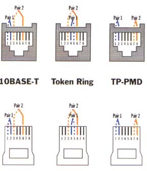
UTP JACKS for all network connections
All you need is here. Be very careful with colors 'cause although I thought do not have anything to do with the cable, they really do!!
 |
 |